

Summary
This model has an initial resolution of about 2 pc and a finest grid after zooming of about 400 AU.Simulated using Ramses 3 (MHD)
Parameters
| Parameter | Value |
|---|---|
| Height0 | $150$ |
| boxlen_pc | $998.16$ |
| boxlen | 1000 |
| bx_bound | $0.5$ |
| by_bound | $0$ |
| bz_bound | $0$ |
| dens0 | $1.5$ |
| time_Myr | $8.9237$ |
| turb | $5$ |
| Tsat | 1.d5 |
| boxlen_codeunits | $1000$ |
| cooling | |
| courant_factor | $0.8$ |
| eff_sn | $0.1$ |
| exp_refine | 10*10 |
| gamma | $1.66667$ |
| gravity_type | $-1$ |
| hydro | |
| isothermal | .false. !.true. |
| jeans_refine | 11*10. |
| levelmax | $20$ |
| levelmin | $7$ |
| m_refine | 0.001,0.001,0.001,0.00001,0.004,0.004,0.001 |
| ncpu | $4096$ |
| nexpand | $1$ |
| nstep_coarse | $1060$ |
| nsubcycle | 2*1,13*2 |
| poisson | |
| pressure_fix | |
| r_refine | 500.,400.,300.,250.,150.,130.,6*100. |
| riemann | 'hlld' |
| riemann2d | 'hlld' |
| slope_type | $1$ |
| smallc | $0.01$ |
| smallr | $0.0001$ |
| time | $0.110892$ |
| unit_d | $2.32474e-24$ |
| unit_l | $3080000000000000000000$ |
| unit_t | $2539507940032080$ |
| x_refine | 250.,200.,150.,10*125. |
| y_refine | 250.,200.,150.,10*130. |
| z_refine | 13*500. |
Applied physics
- Self-gravity
- Self-Gravity is applied.
- Hydrodynamics
- Hydrodynamical equations are solved
- Magnetohydrodynamics
- Ideal magneto-hydrodynamics is resolved.
- Supernovae feedback
- Supernovae feedback is applied around the densest cell in the simulation at a rate equal to the Milky way rate.
Snapshots
FRIG_00180 (t=$8.9237 \; \textrm{kyr}$)
descrip_snapshot
Catalogs :
Datafiles:
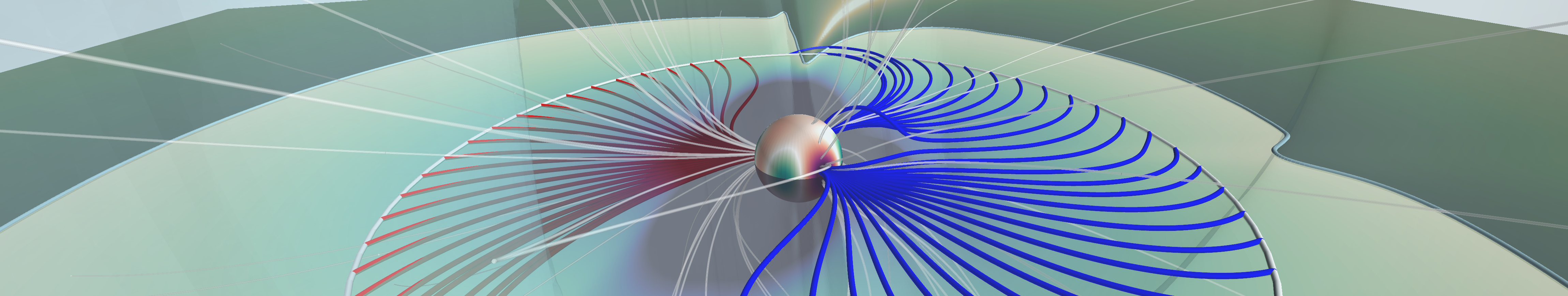
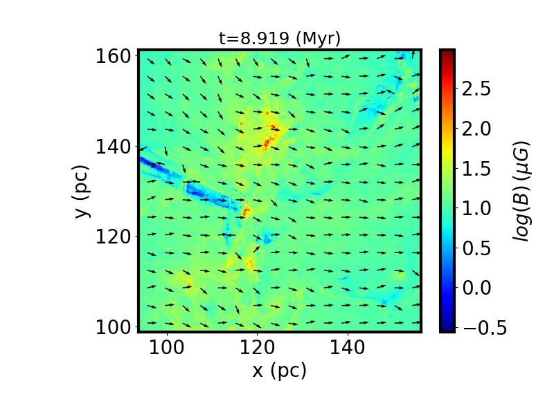
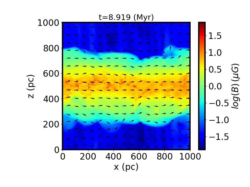
Density weighted integrated magnetic intensity along the z-direction. The arrows represent the projected direction of the integrated B in the xy-plane.
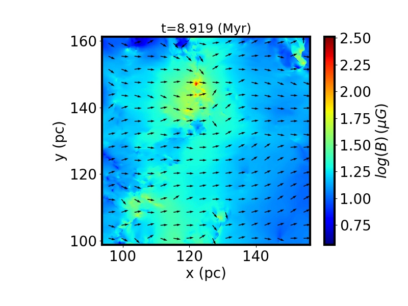
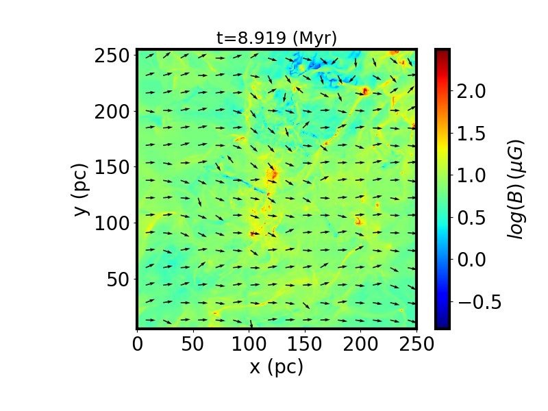
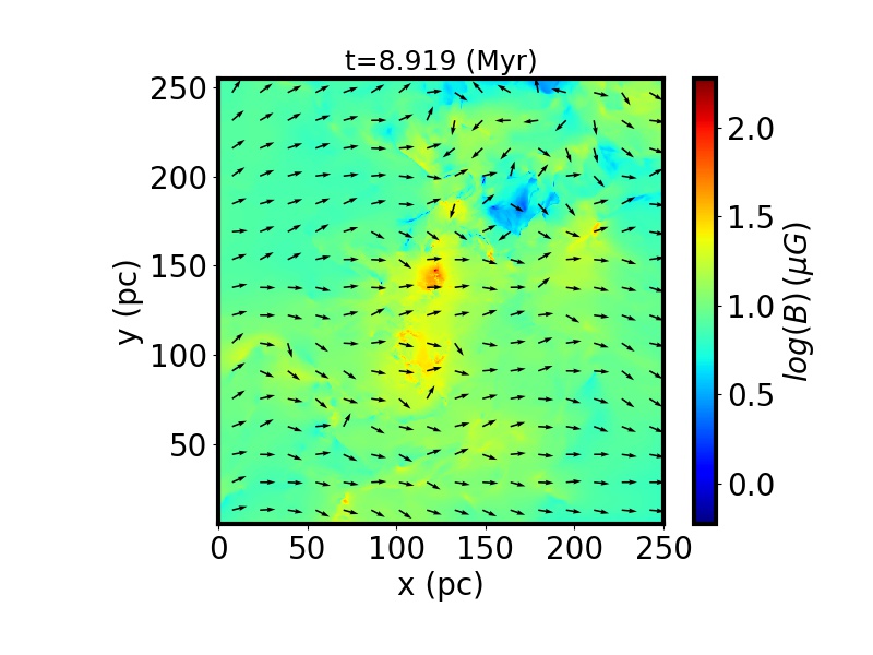
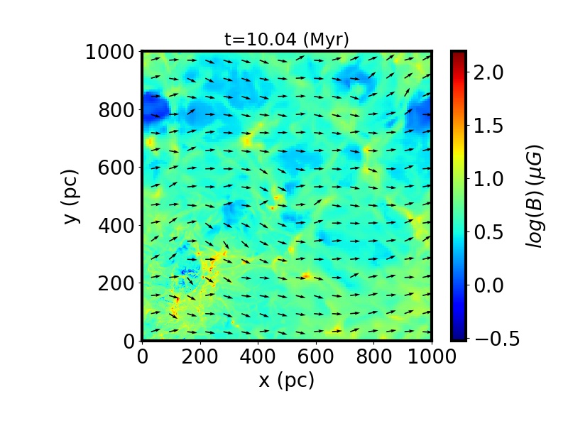
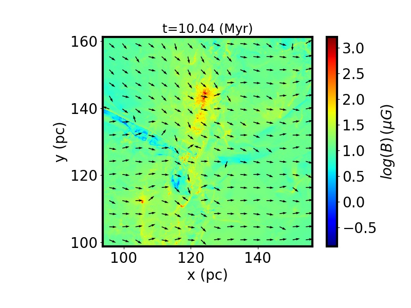
Cut of the magnetic intensity in the xy-plane. The arrows represent the projected direction of B in the xy-plane.
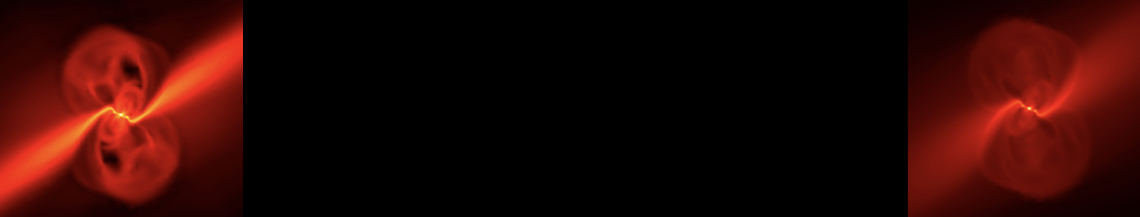
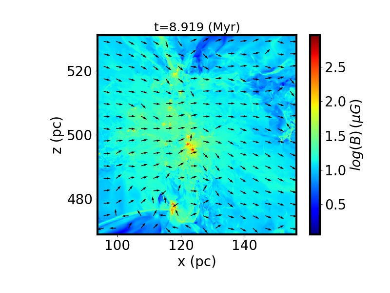
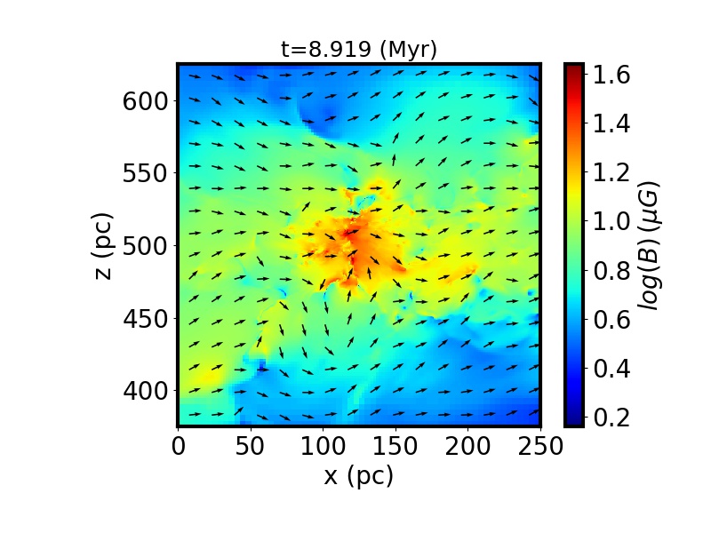
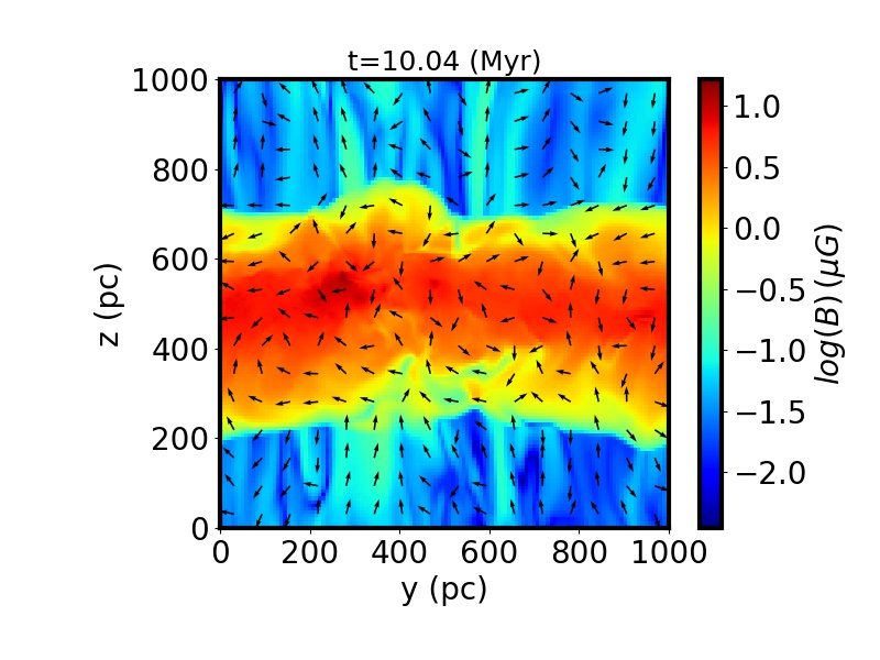
Density weighted integrated magnetic intensity along the y-direction. The arrows represent the projected direction of the integrated B in the xz-plane.
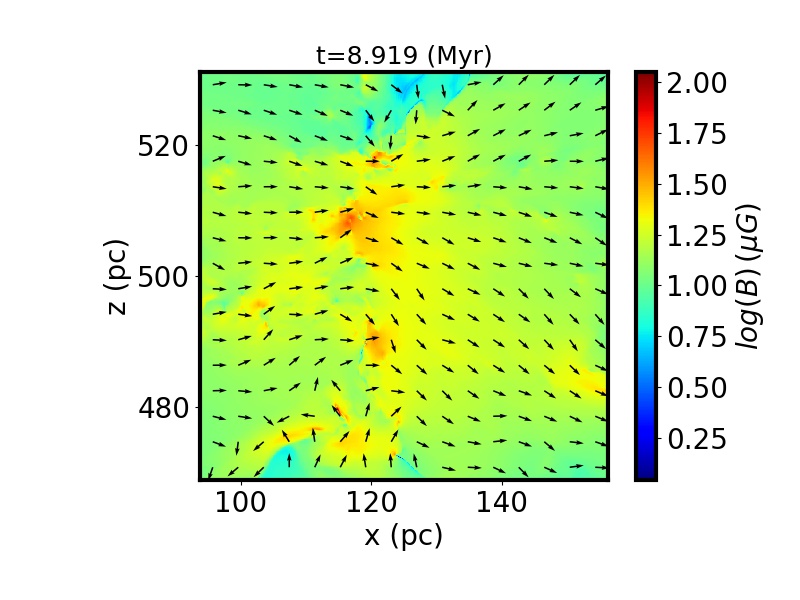
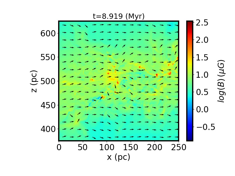
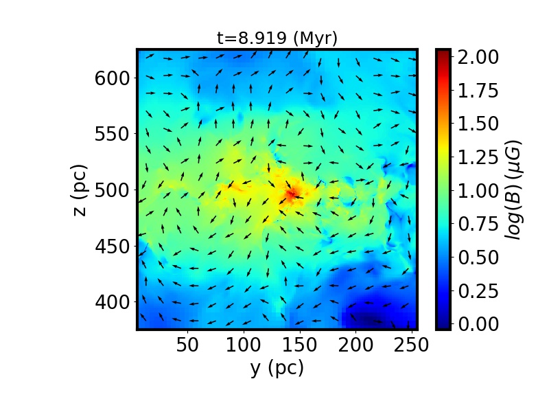
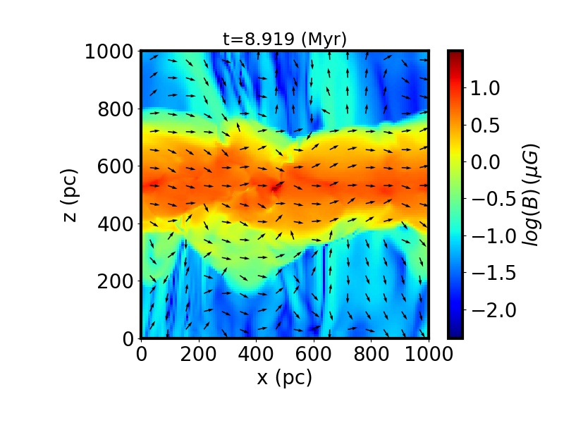
Cut of the magnetic intensity in the xz-plane. The arrows represent the projected direction of B in the xz-plane.
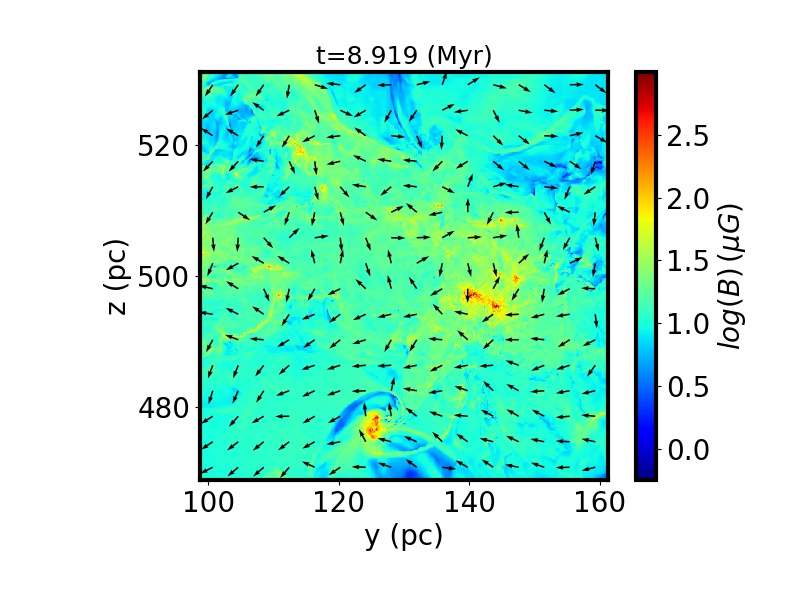
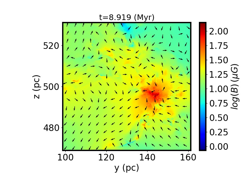
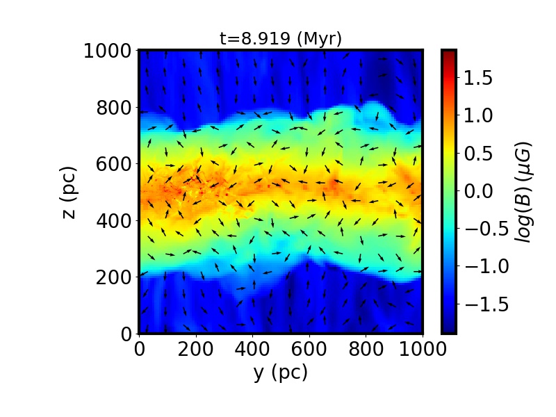
Density weighted integrated magnetic intensity along the y-direction. The arrows represent the projected direction of B in the yz-plane.
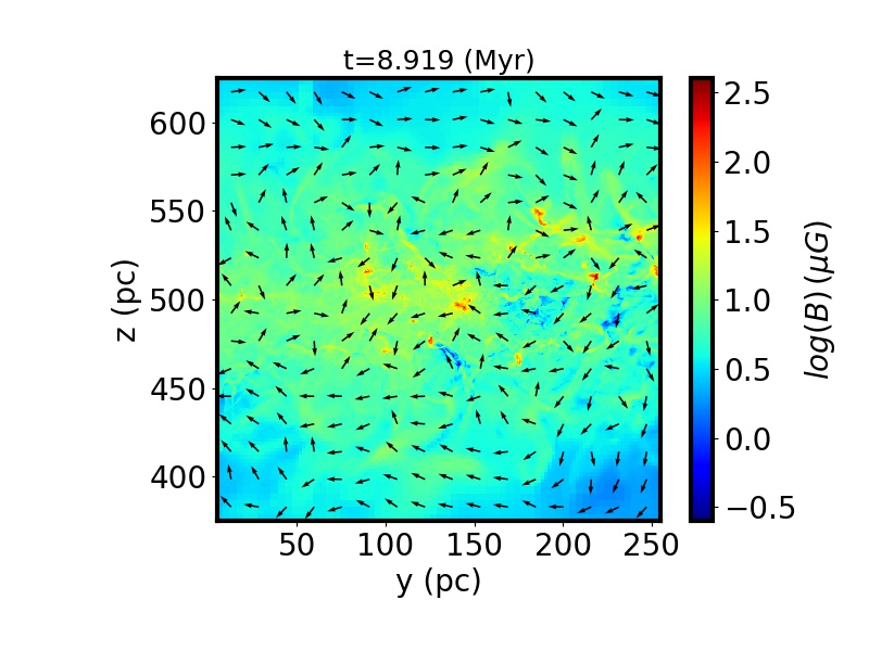
Cut of the magnetic intensity in the yz-plane. The arrows represent the projected direction of B in the yz-plane.
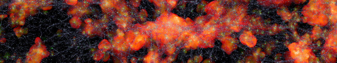
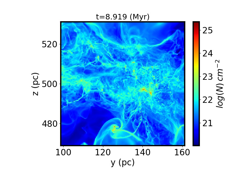
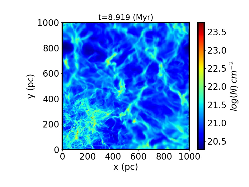
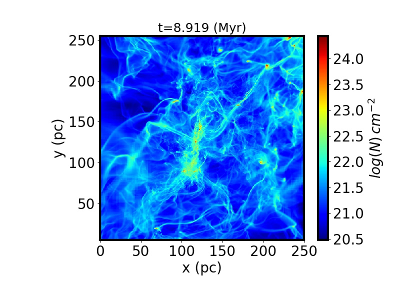
Column density along the z-direction
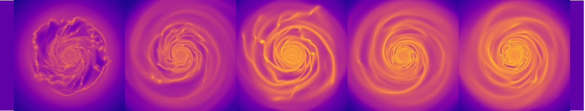
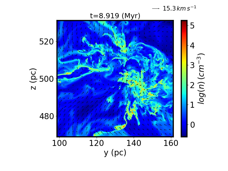
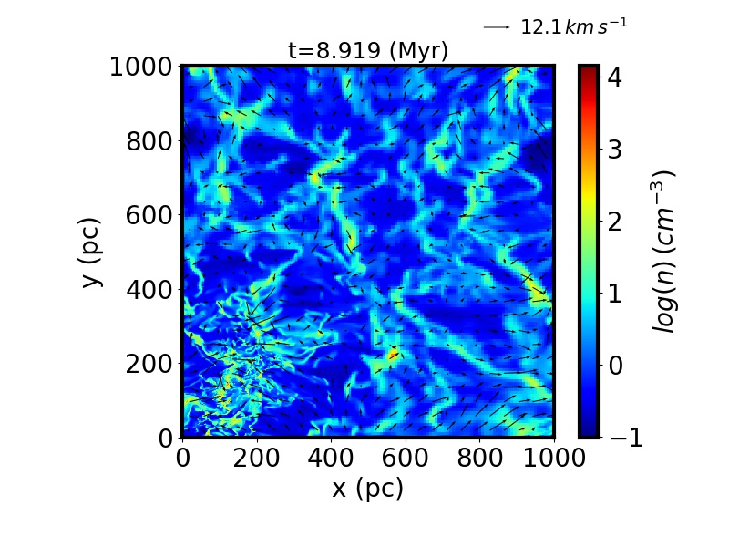
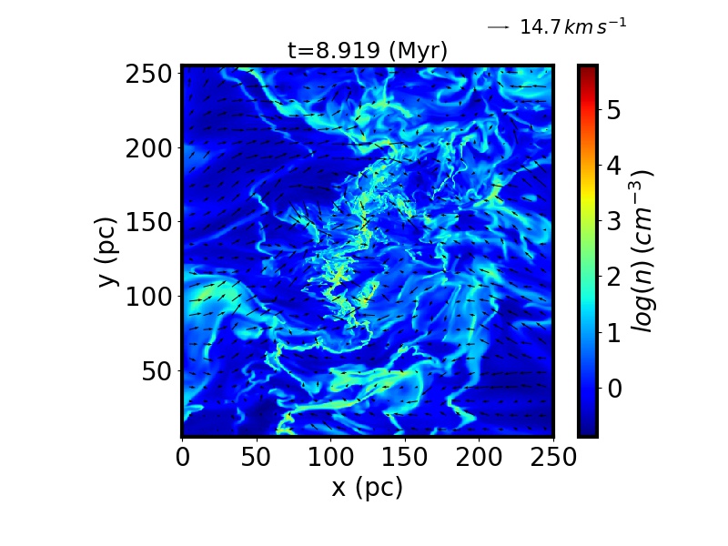
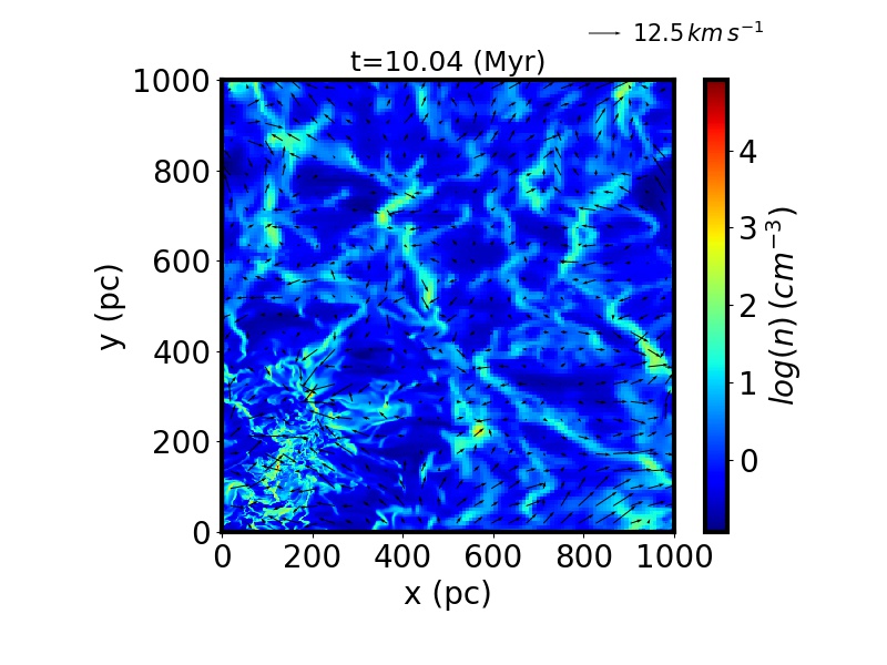
Density in the xy-plane. The arrows represent the velocity field in the xy plane.
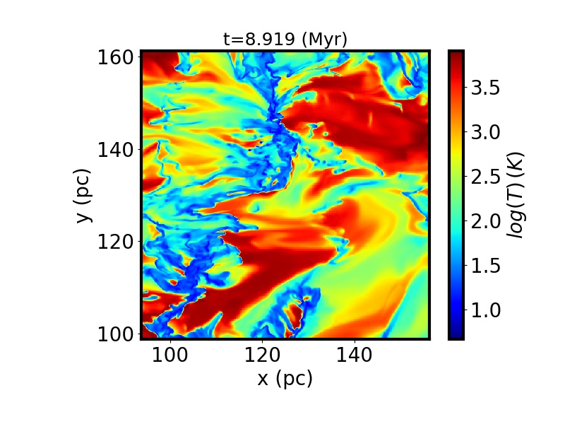
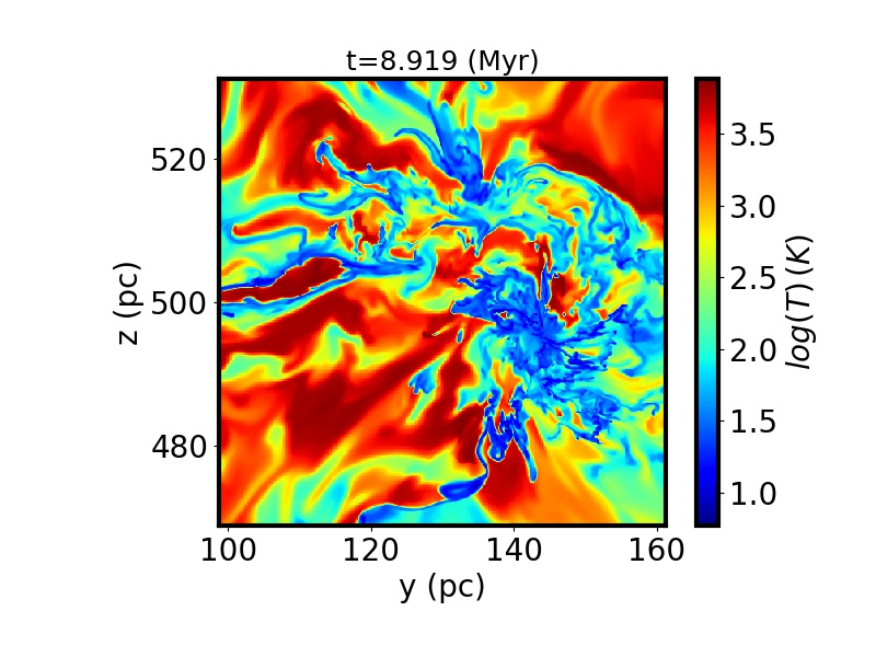
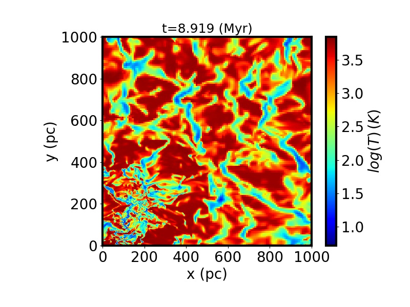
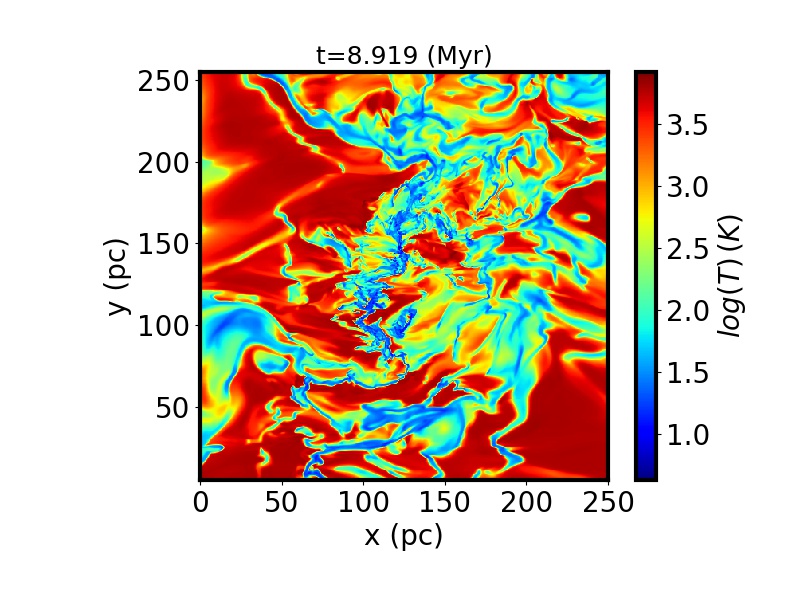
Temperature in the xy-plane.
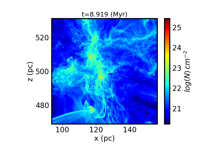
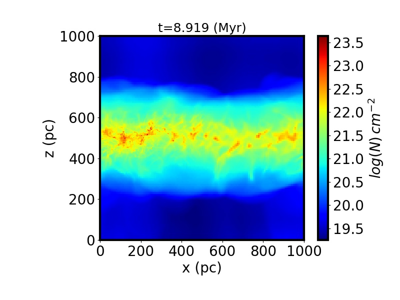
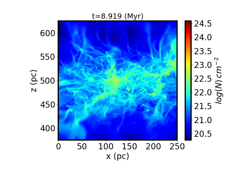
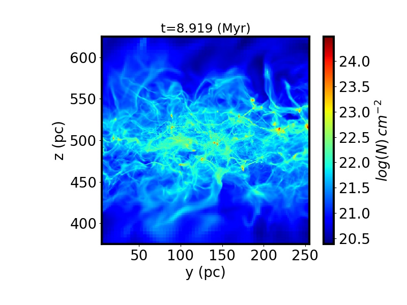
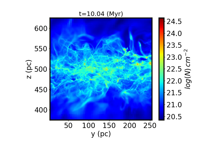
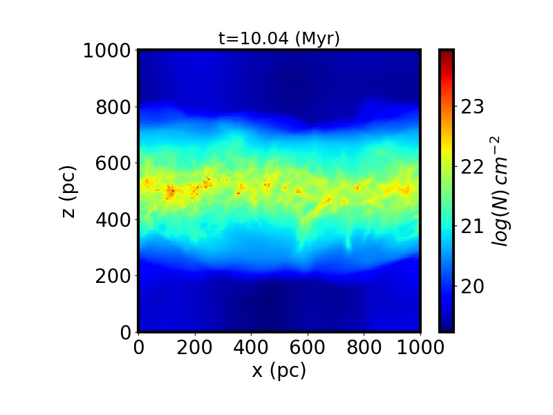
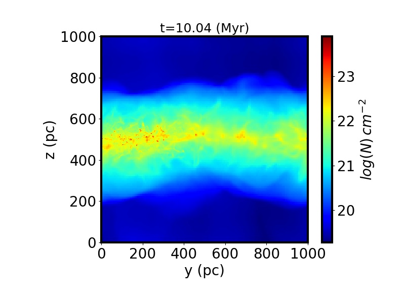
Column density along the y-direction.
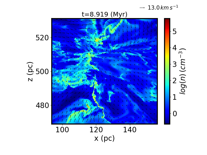
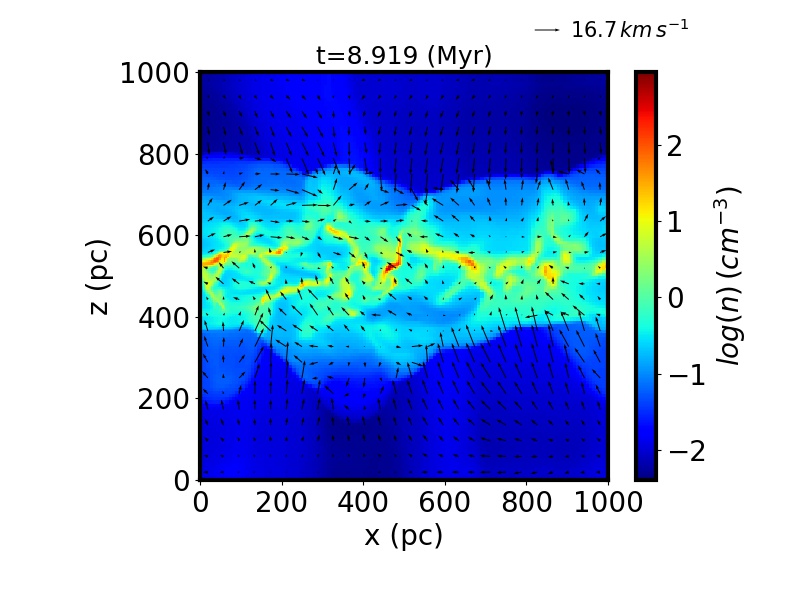
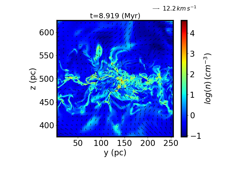
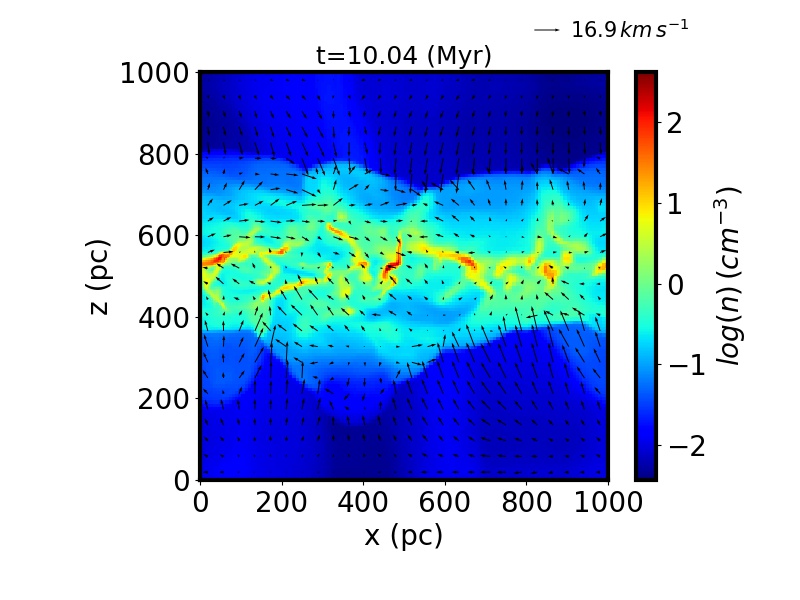
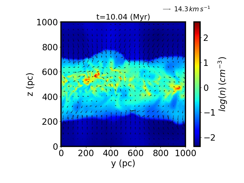
Density in the xz-plane. The arrows represent the velocity field in the xz-plane.
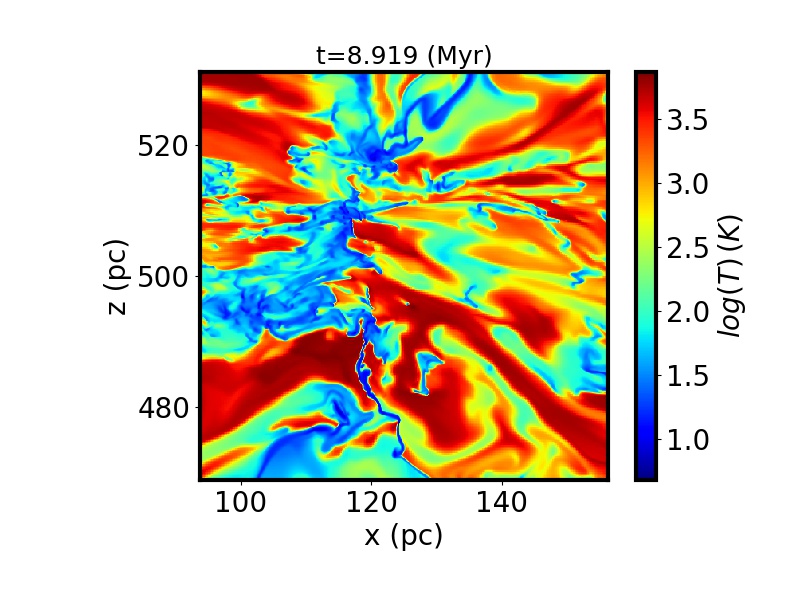
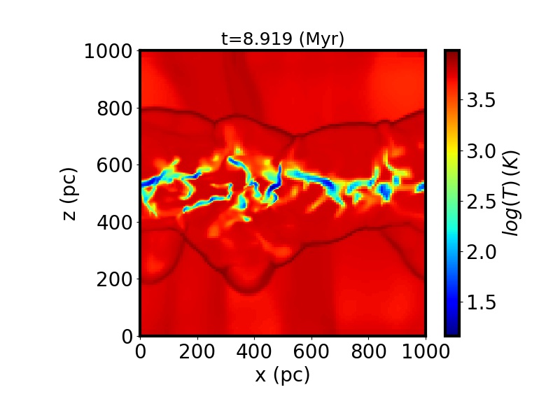
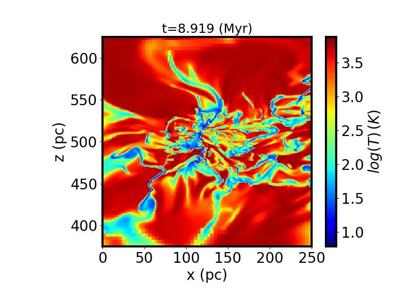
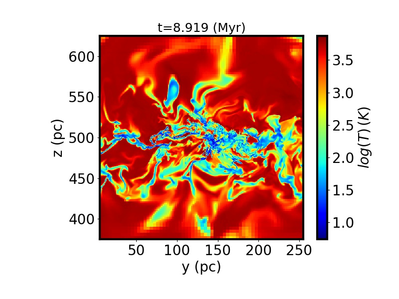
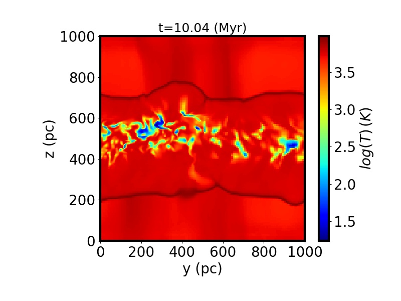
Temperature in the xz-plane.
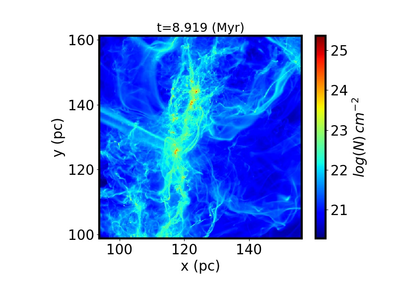
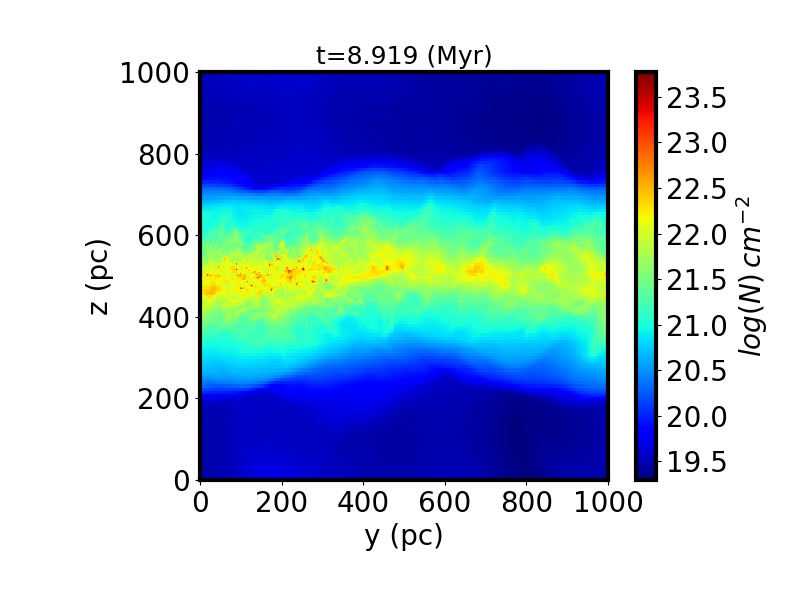
Column density along the x-direction.
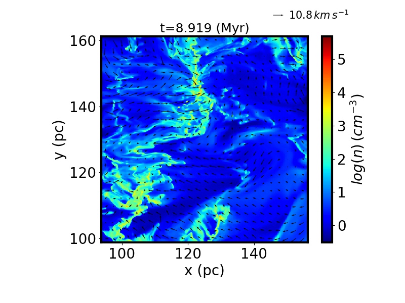
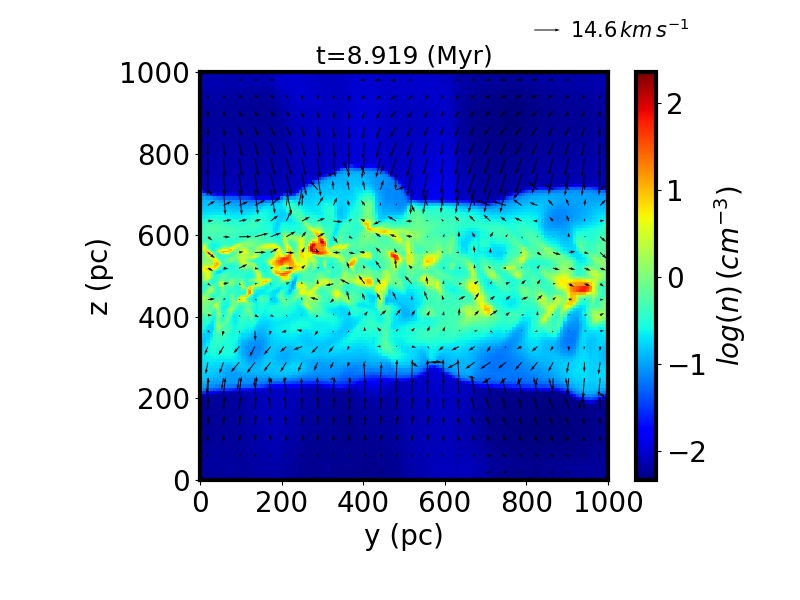
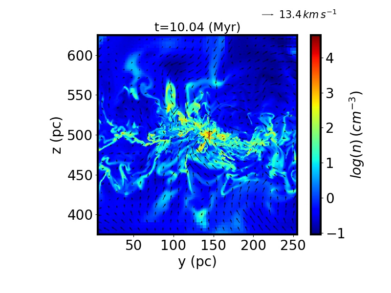
Density in the yz-plane. The arrows represent the velocity field in the yz-plane.
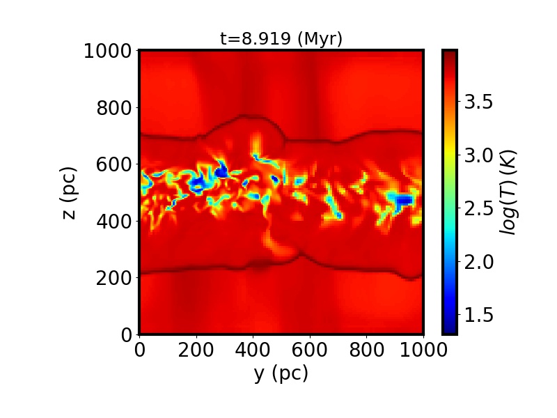
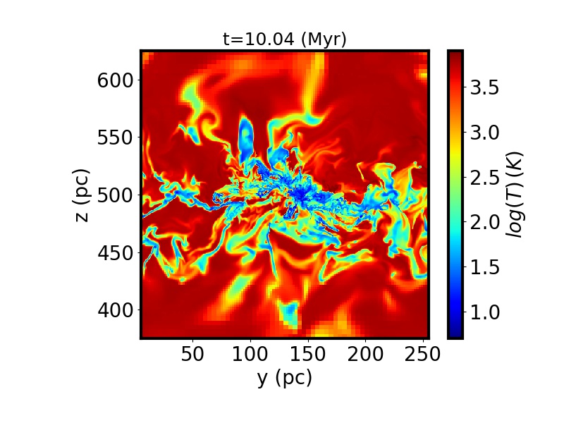
Temperature in the yz-plane.
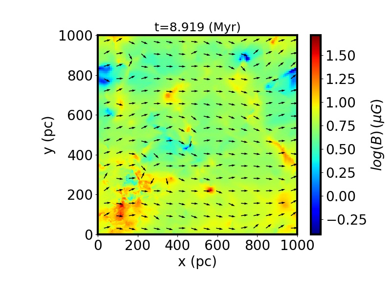
Density weighted integrated magnetic intensity along the z-direction. The arrows represent the projected direction of the integrated B in the xy-plane.
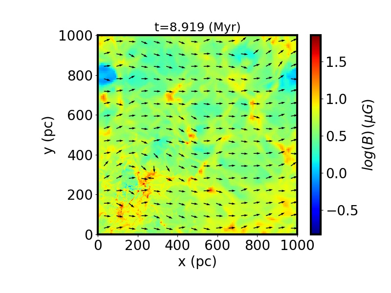
Cut of the magnetic intensity in the xy-plane. The arrows represent the projected direction of B in the xy-plane.
Density weighted integrated magnetic intensity along the y-direction. The arrows represent the projected direction of the integrated B in the xz-plane.
Cut of the magnetic intensity in the xz-plane. The arrows represent the projected direction of B in the xz-plane.
Density weighted integrated magnetic intensity along the y-direction. The arrows represent the projected direction of B in the yz-plane.
Cut of the magnetic intensity in the yz-plane. The arrows represent the projected direction of B in the yz-plane.
Column density along the z-direction
Density in the xy-plane. The arrows represent the velocity field in the xy plane.
Temperature in the xy-plane.
Column density along the y-direction.
Density in the xz-plane. The arrows represent the velocity field in the xz-plane.
Temperature in the xz-plane.
Column density along the x-direction.
Density in the yz-plane. The arrows represent the velocity field in the yz-plane.
Temperature in the yz-plane.
Density weighted integrated magnetic intensity along the z-direction. The arrows represent the projected direction of the integrated B in the xy-plane.
Cut of the magnetic intensity in the xy-plane. The arrows represent the projected direction of B in the xy-plane.
Density weighted integrated magnetic intensity along the y-direction. The arrows represent the projected direction of the integrated B in the xz-plane.
Cut of the magnetic intensity in the xz-plane. The arrows represent the projected direction of B in the xz-plane.
Density weighted integrated magnetic intensity along the y-direction. The arrows represent the projected direction of B in the yz-plane.
Cut of the magnetic intensity in the yz-plane. The arrows represent the projected direction of B in the yz-plane.
Column density along the z-direction
Density in the xy-plane. The arrows represent the velocity field in the xy plane.
Temperature in the xy-plane.
Column density along the y-direction.
Density in the xz-plane. The arrows represent the velocity field in the xz-plane.
Temperature in the xz-plane.
Column density along the x-direction.
Density in the yz-plane. The arrows represent the velocity field in the yz-plane.
Temperature in the yz-plane.
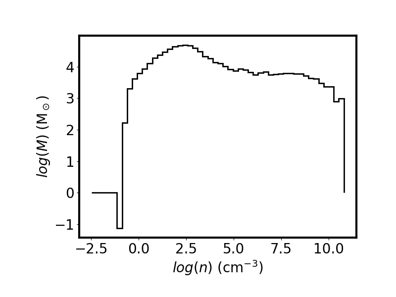
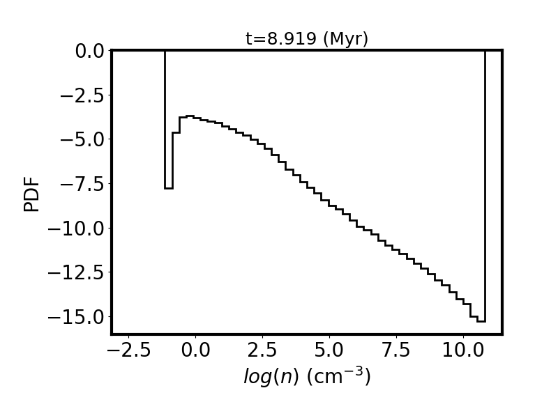
Mass weighted density PDF.
Volume weighted density PDF.
Mass weighted temperature.
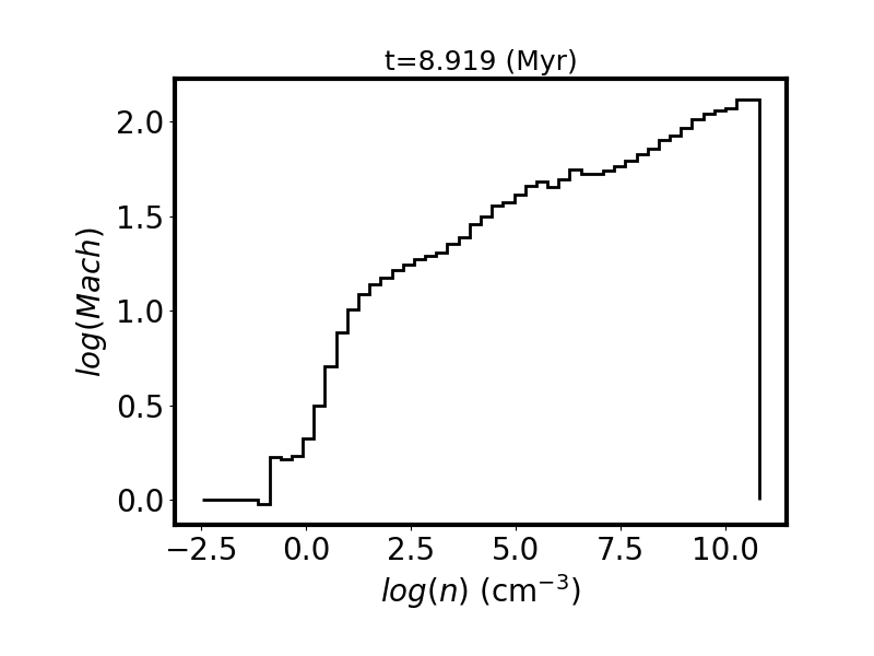
Mass weighted Mach number.
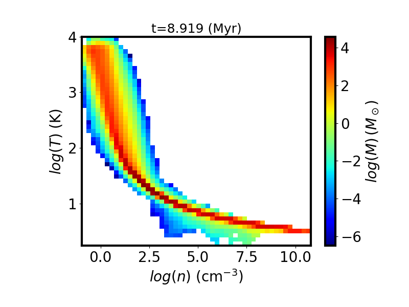
Mass weighted bidimentional histogram of the temperature vs density
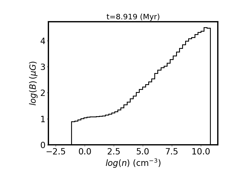
Volume weighted magnetic intensity.
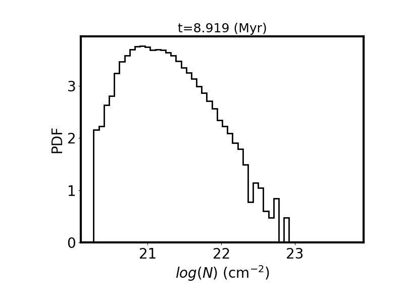
Surface weighted column density PDF.
FRIG_00249 (t=$10.0495 \; \textrm{kyr}$)
descrip_snapshot
Catalogs :
Datafiles:
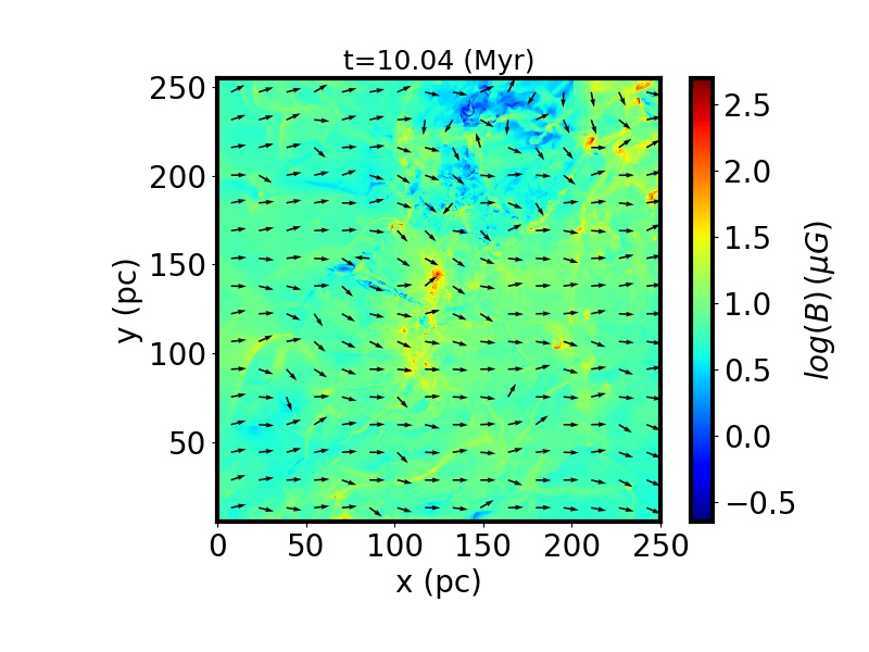
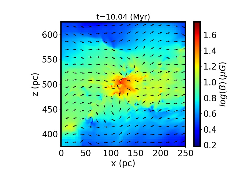
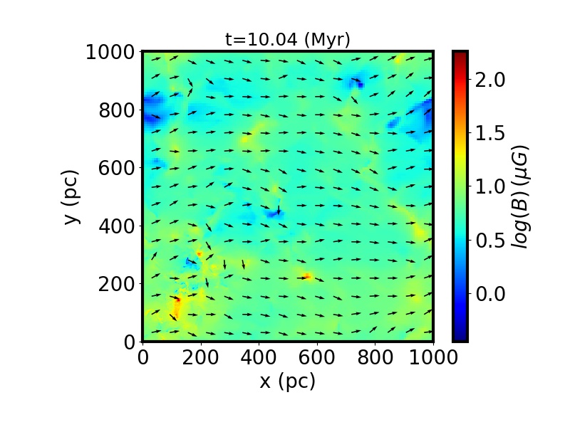
Density weighted integrated magnetic intensity along the z-direction. The arrows represent the projected direction of the integrated B in the xy-plane.
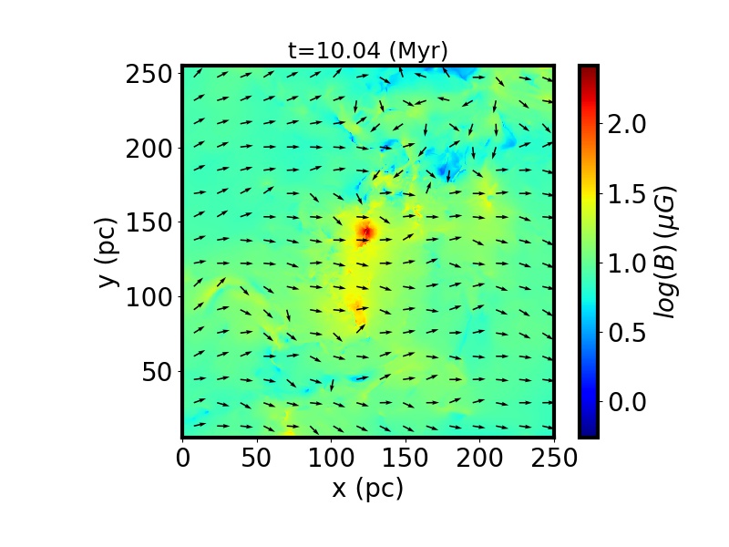
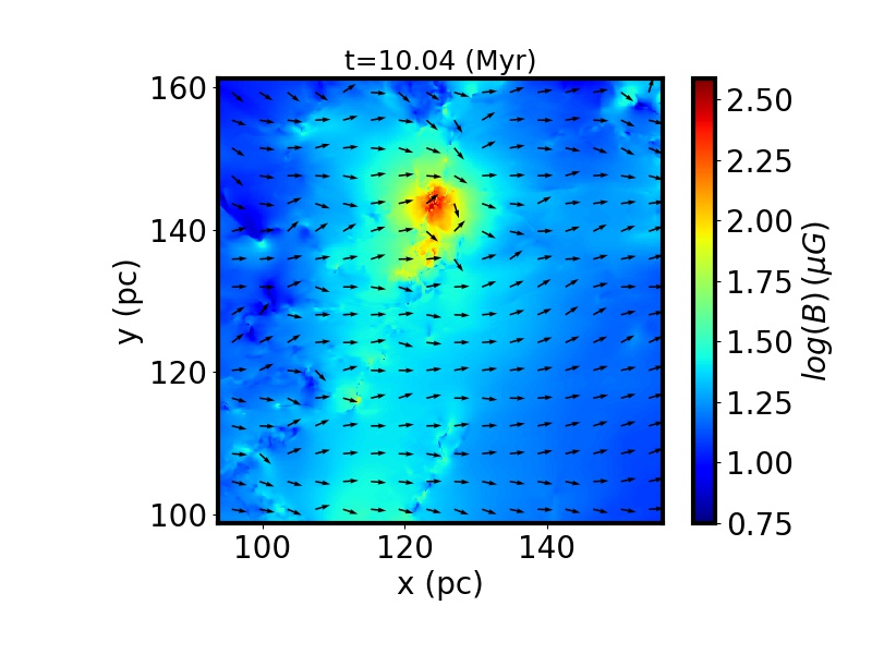
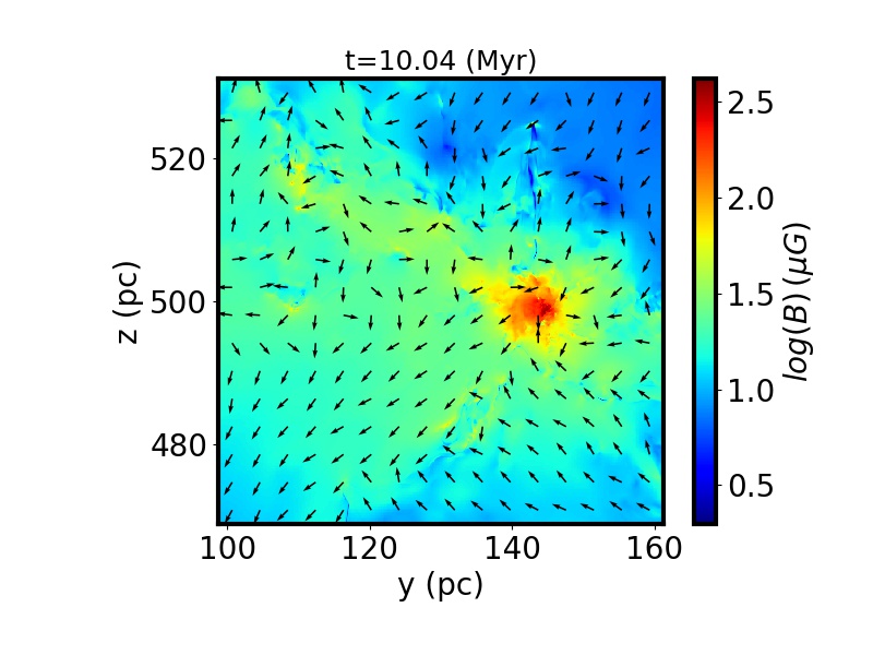
Cut of the magnetic intensity in the xy-plane. The arrows represent the projected direction of B in the xy-plane.
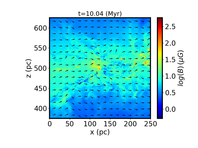
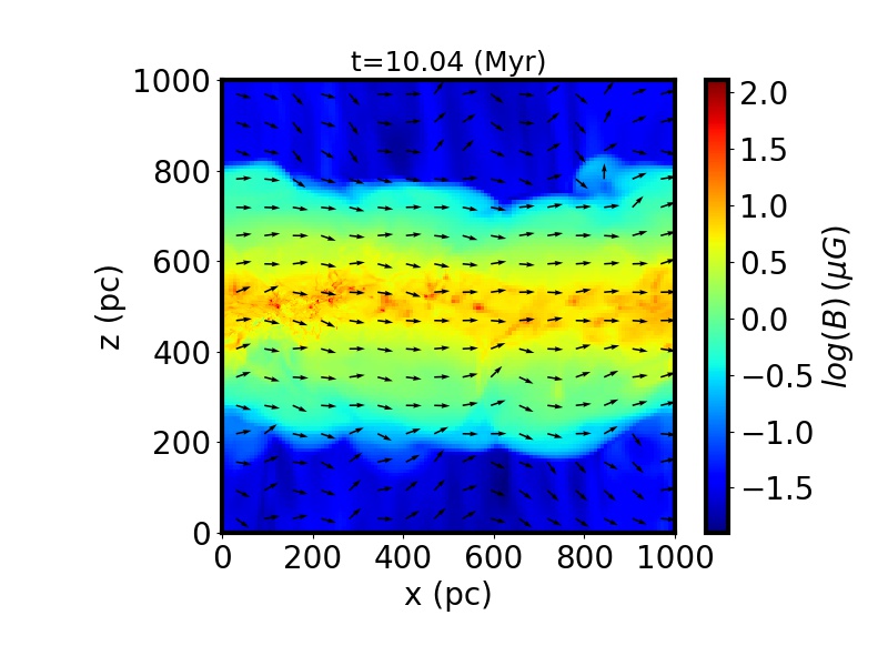
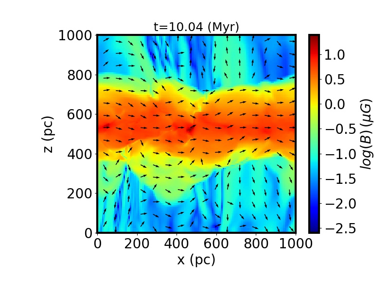
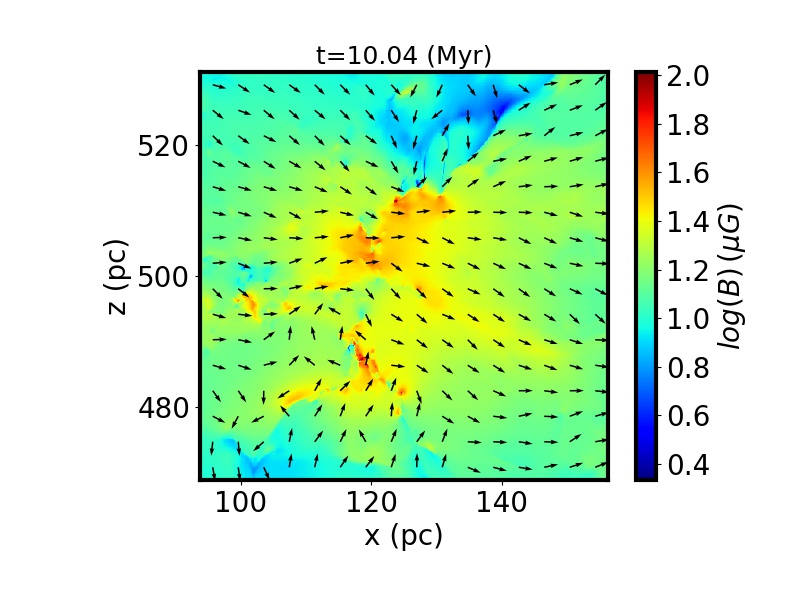
Density weighted integrated magnetic intensity along the y-direction. The arrows represent the projected direction of the integrated B in the xz-plane.
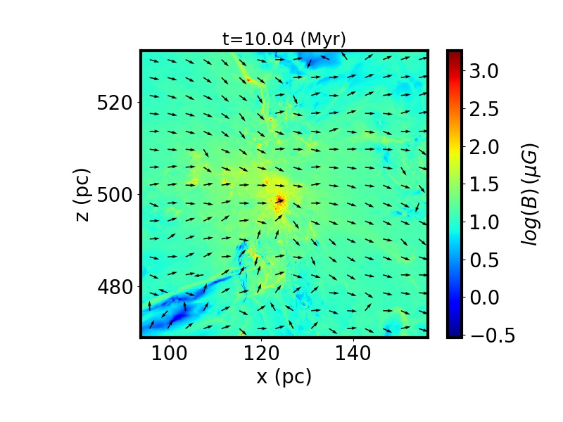
Cut of the magnetic intensity in the xz-plane. The arrows represent the projected direction of B in the xz-plane.
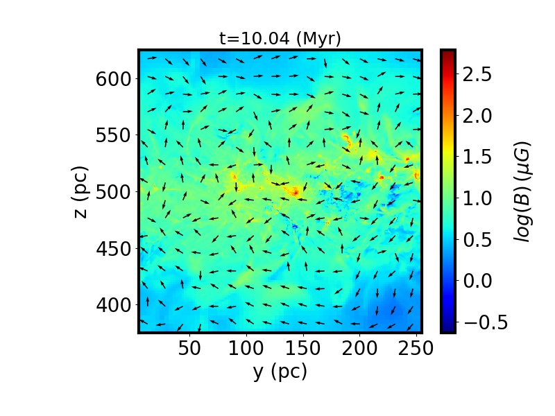
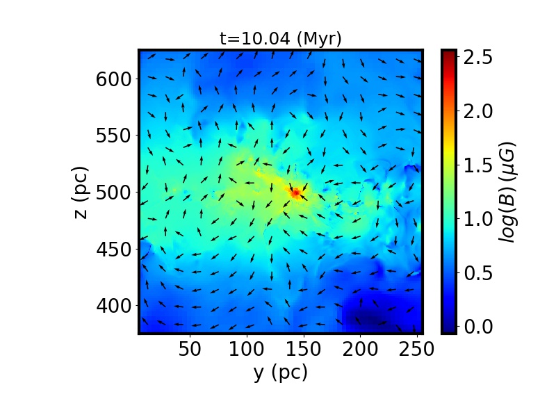
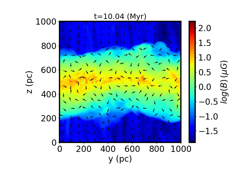
Density weighted integrated magnetic intensity along the y-direction. The arrows represent the projected direction of B in the yz-plane.
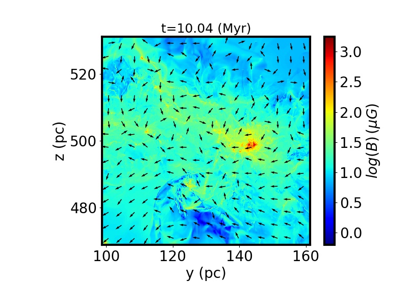
Cut of the magnetic intensity in the yz-plane. The arrows represent the projected direction of B in the yz-plane.
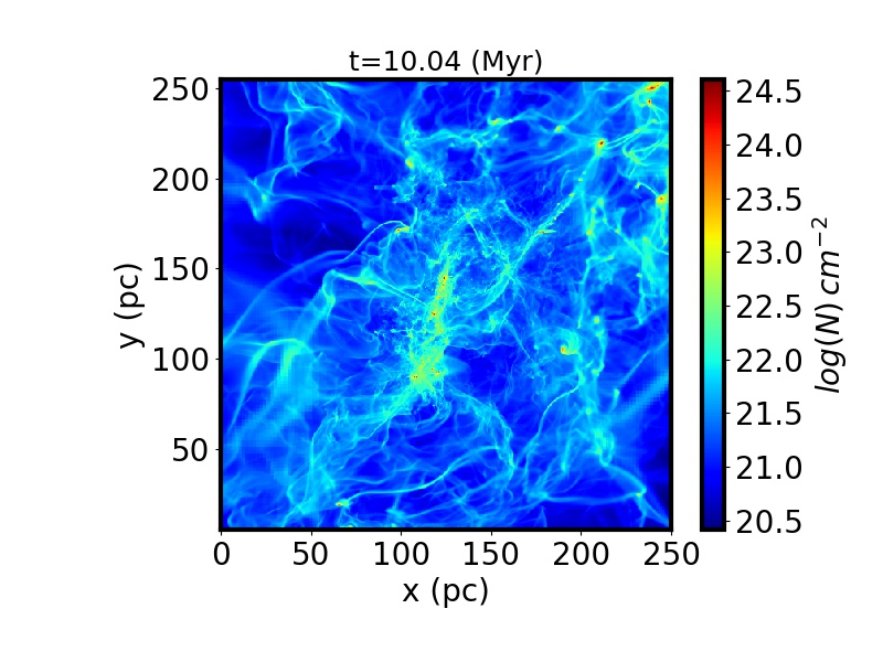
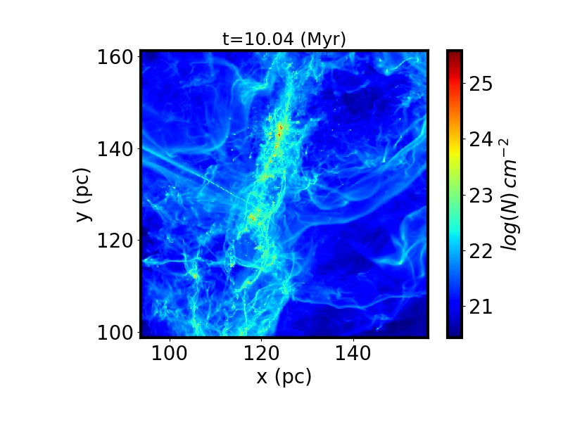
Column density along the z-direction
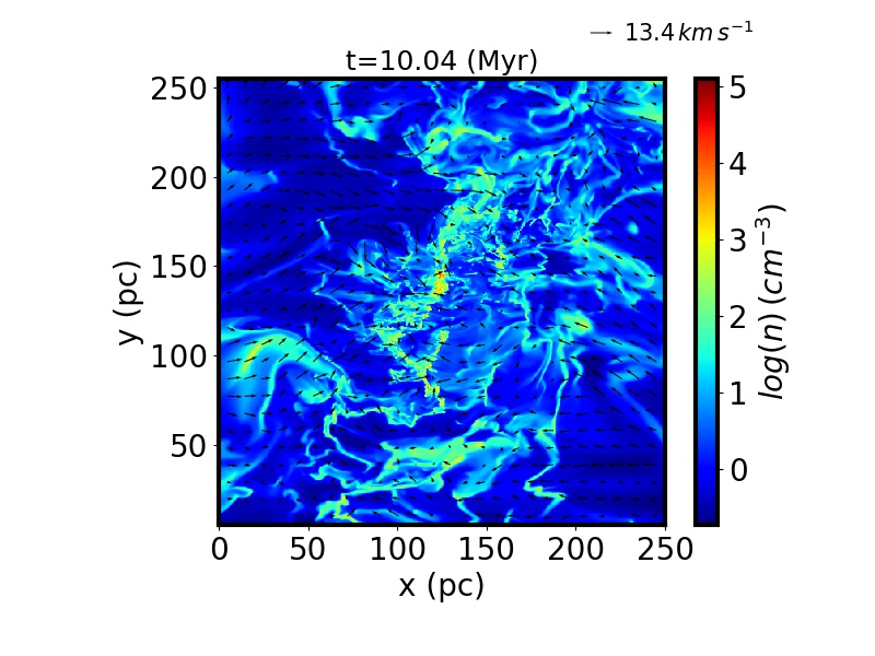
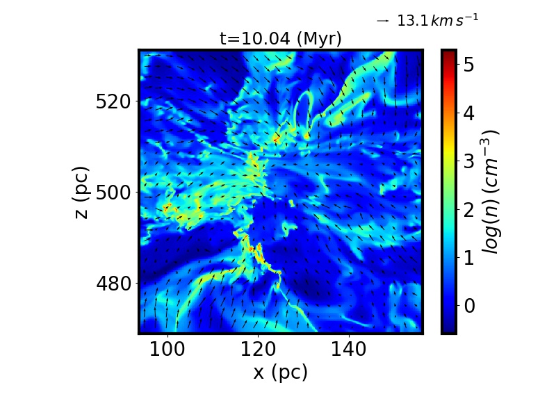
Density in the xy-plane. The arrows represent the velocity field in the xy plane.
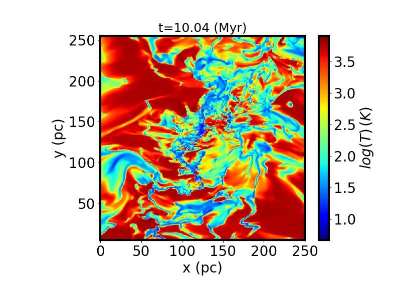
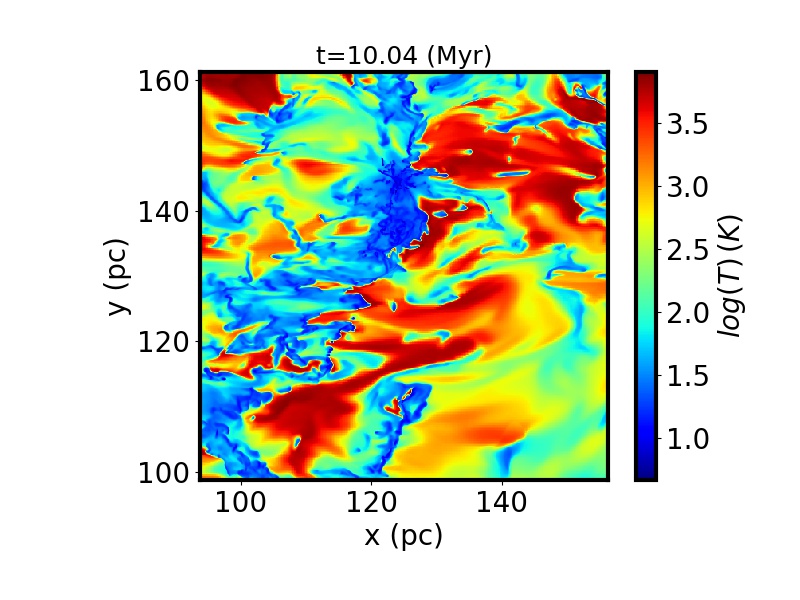
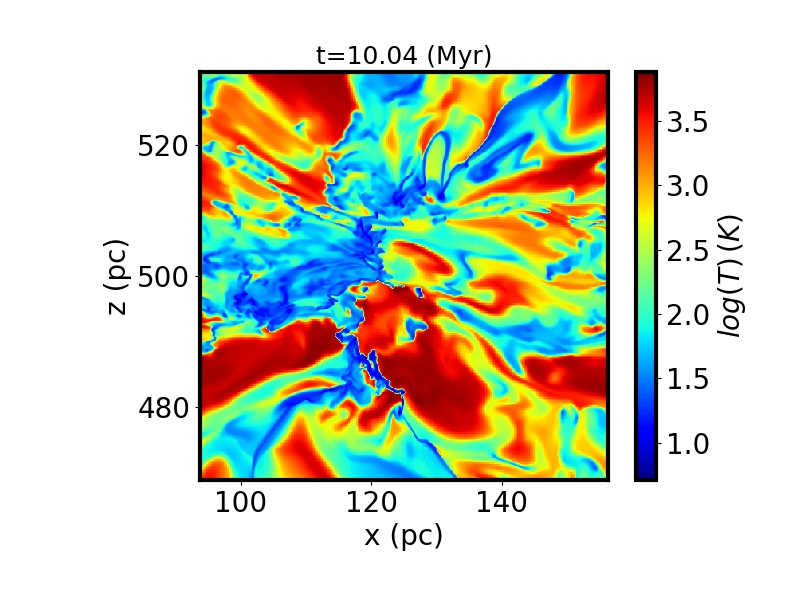
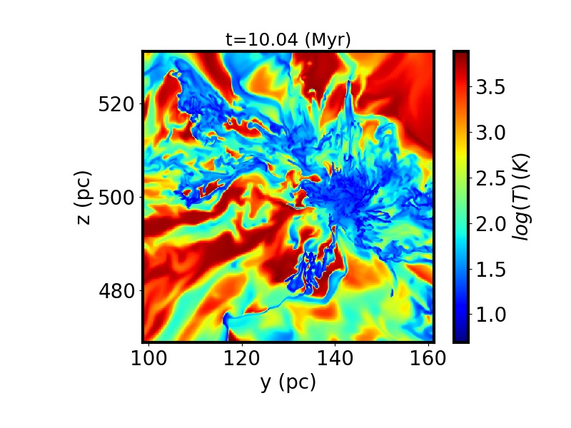
Temperature in the xy-plane.
Column density along the y-direction.
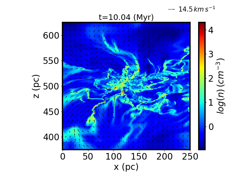
Density in the xz-plane. The arrows represent the velocity field in the xz-plane.
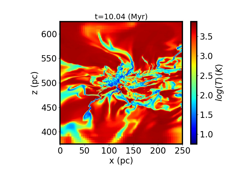
Temperature in the xz-plane.
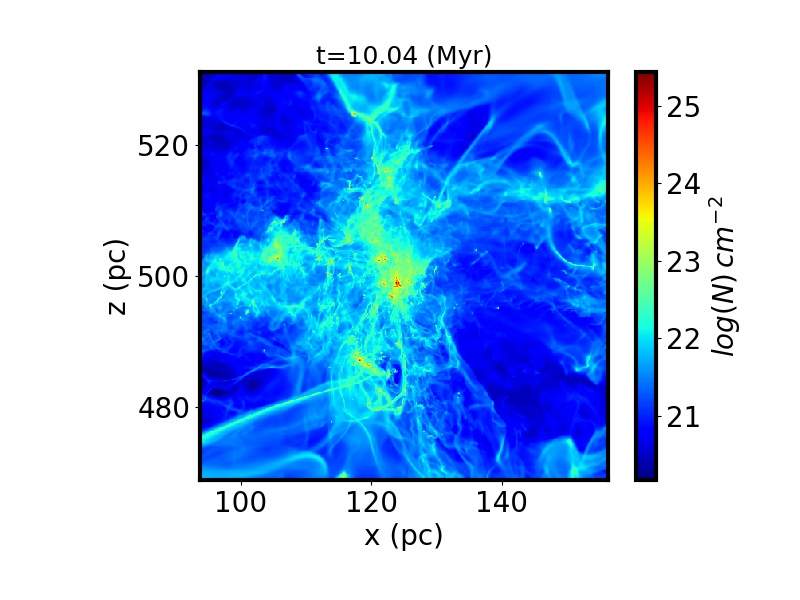
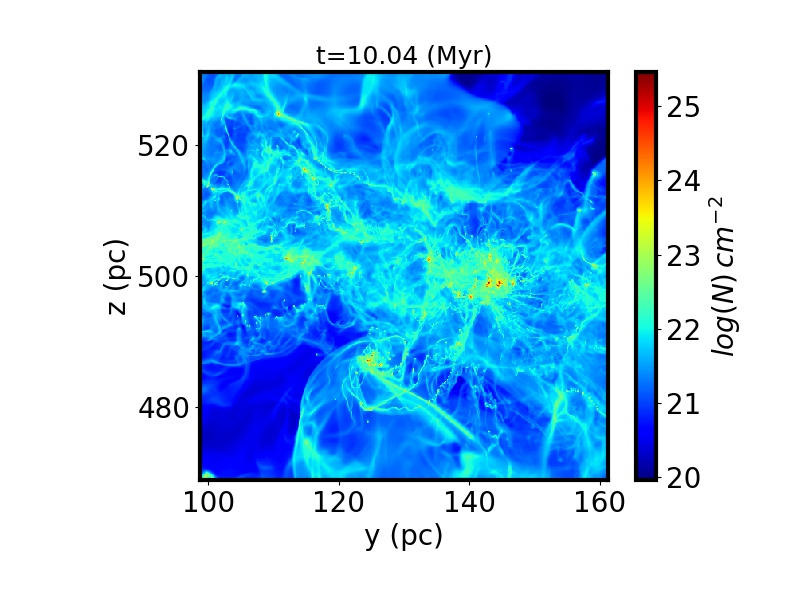
Column density along the x-direction.
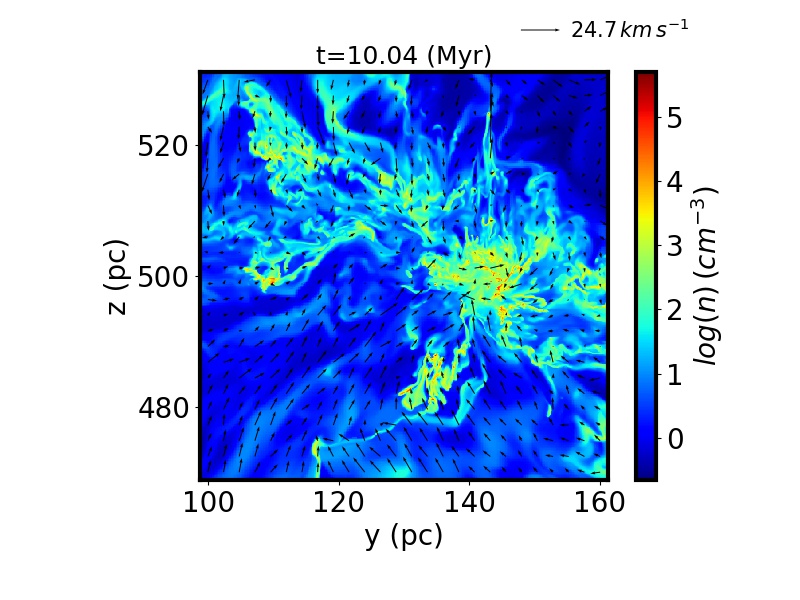
Density in the yz-plane. The arrows represent the velocity field in the yz-plane.
Temperature in the yz-plane.
Density weighted integrated magnetic intensity along the z-direction. The arrows represent the projected direction of the integrated B in the xy-plane.
Cut of the magnetic intensity in the xy-plane. The arrows represent the projected direction of B in the xy-plane.
Density weighted integrated magnetic intensity along the y-direction. The arrows represent the projected direction of the integrated B in the xz-plane.
Cut of the magnetic intensity in the xz-plane. The arrows represent the projected direction of B in the xz-plane.
Density weighted integrated magnetic intensity along the y-direction. The arrows represent the projected direction of B in the yz-plane.
Cut of the magnetic intensity in the yz-plane. The arrows represent the projected direction of B in the yz-plane.
Column density along the z-direction
Density in the xy-plane. The arrows represent the velocity field in the xy plane.
Temperature in the xy-plane.
Column density along the y-direction.
Density in the xz-plane. The arrows represent the velocity field in the xz-plane.
Temperature in the xz-plane.
Column density along the x-direction.
Density in the yz-plane. The arrows represent the velocity field in the yz-plane.
Temperature in the yz-plane.
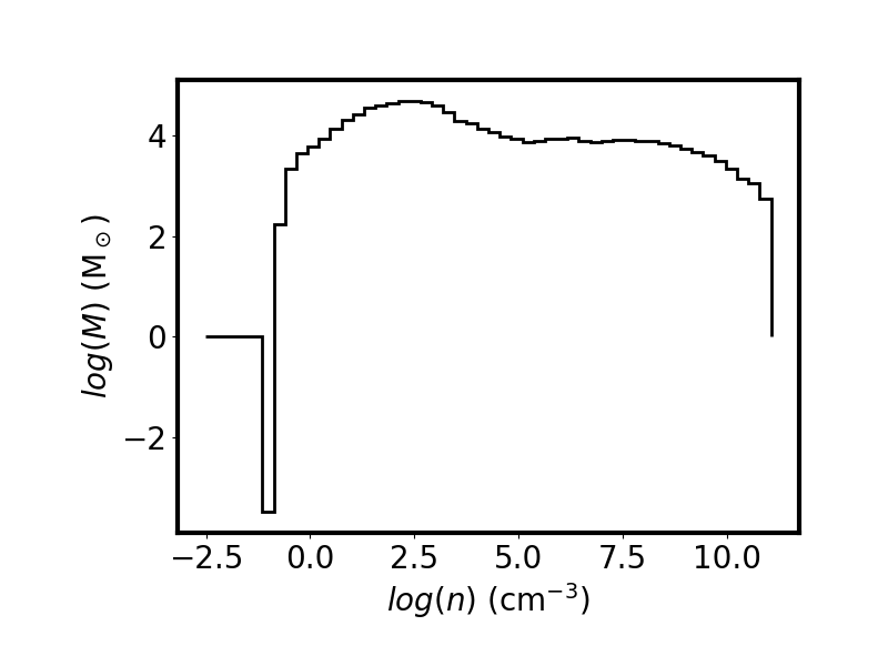
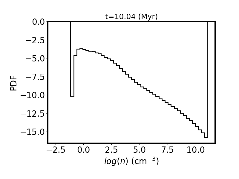
Mass weighted density PDF.
Volume weighted density PDF.
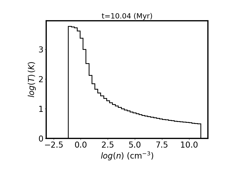
Mass weighted temperature.
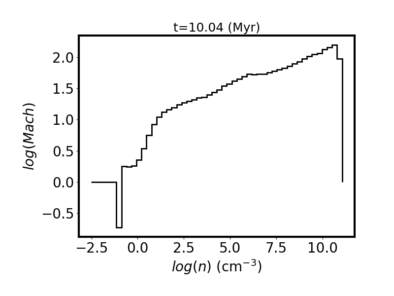
Mass weighted Mach number.
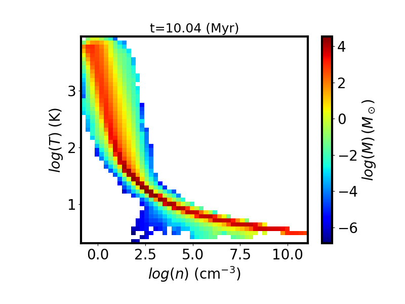
Mass weighted bidimentional histogram of the temperature vs density
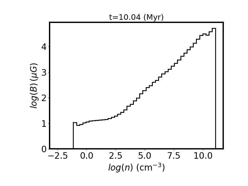
Volume weighted magnetic intensity.
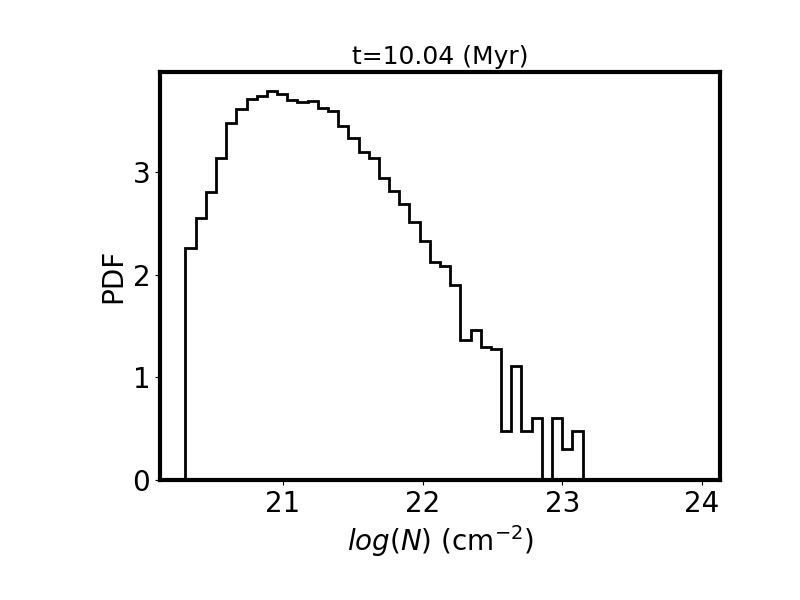
Surface weighted column density PDF.
